 Simple code ñ trying to keep it as small as possible.
Sphere Tessellation 101:
"The Art of Making Spheres out of Triangles"
Dedication: To My Father, Celebrating his 66th Birthday ñ June 3rd.
Introduction
I happened to be developing an algorithm to generate spheres when I noticed the Hugi Birthday announcement. Since it was fresh in my mind, I figured I would document a method I've created to build spheres as a little birthday present. So Happy Birthday Hugi! Here is a tutorial for Hugi 27! :)
That having been mentioned, I'm not a math major ñ so this is not the most efficient method for generating spheres. Also, this is really a first cut of the algorithm with lots of areas to optimize. I'll point some of those areas out... other area's you will have to find on your own. However, I promise that by the end of this tutorial, you will have a workable algorithm to generate spheres; which is reasonably compact; and you will probably understand it. Yes, that's right, a tutorial based on math in informal language that is understandable! Wow!
Objective
Begin at the beginning. Or at least that's what Einstein said. So... I feel it's suitable to start with a simple question: "What are we trying to accomplish?" For our purposes; I was interested in generating a sphere tessellation algorithm, with a small code footprint. The algorithm should have the following features:
Simple code ñ trying to keep it as small as possible.
The number of triangles is not critical ñ and can be cooked to "simplify the math"
Floating-point operations are permitted; since it's safe to assume most target systems will have an FPU. Note ñ this is a change for us old skoolers, since this wasn't possible in the past. Cos(x) and Sin(x) are cool as they are directly supported; but funkier transcendental functions should be avoided because they don't have direct support. (i.e.... no direct operation in the FPU)
Generating the sphere as a single DrawPrimitive for use in Direct 3d. Implementation should be as a Triangle Strip ñ not a triangle list; even if degenerate triangles are required to do this.
With these objectives in mind, I began the great internet search for a code snippet. [Hey.. do I look like I'm made of time?]. And I found bubkus. Nothing.... Nada... the big donut. Direct 3d has the D3DXCreateSphere function, but that will kill your code size as soon as you include D3DX. There is code in the Direct x 7.0 SDK (going back a few years)... but it's about a page long... and much more complicated than this simple question. The other algorithms I found were similar. I had the feeling this could be done in less than a half page of code... so I started developing this algorithm.
First Principles: How will it work?
While I searched the blue nowhere for the answer, I noticed that almost all the algorithms were based on dividing a sphere into "bands". It was as if you sliced an onion along the x axis. These slices are stacked to create a sphere. Simple? Well... perhaps a little more complicated. To start, let's define a few terms.
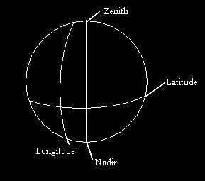
Nadir ñ Southern [lowest in y] pole of the sphere.
Zenith ñ Northern [highest in y] pole of the sphere.
Longitude ñ Angular measure of position from East to West. Longitudinal lines cross the sphere from North to South. On earth, Greenwich (England) is the reference point for the start of longitudinal measure.
Latitude ñ angular measure of position from North to South. Latitudinal lines cross the sphere from East to West. On Earth, the equator is the reference for the reference point latitudinal measure.
Okay, cool... so this should all be pretty much a refresher of geometry / astronomy from high school. The neat thing about this ñ is that the problem of tessellating a sphere was basically solved when cartographers had to take our globe and generate a two dimensional map for it. In our case, we want to take a two-dimensional map (or mesh) and reverse the process to generate a sphere.
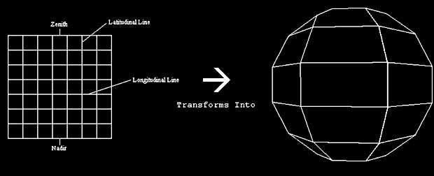
Simple? It's closer... Looking at the figure, you can see that each of the longitudinal lines in a two dimensional grid get pinched ñ so they become circles of varying radiuses. The Zenith and the Nadir get pinched to a single point and the equator is the circle of size r ñ where R is the radius of the sphere. The more quads we use in the grid, the smaller each one becomes, and the finer the tessellation of the sphere becomes.
Spheres and the Art of the Triangle
But wait! We said we need triangles in the objectives. In fact we were more specific ñ we said triangle strips specifically. How does this work? Triangle strips are a list of vertices; where each triangle shares the previous two vertices. The first three vertices define the first triangle in clockwise order. (For culling purposes they must be clockwise to be visible in D3D) Each point after defines another triangle. Now if you look closely at the figure you will notice a cheat. Each second triangle is not defined in a clockwise manner. Direct 3d automatically flips the second triangle winding order to be clockwise; so a mesh can be grown in this manner.
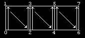
This is an extremely efficient manner to define a grid, as none of those vertices have to be repeated. For the example triangle strip, 6 triangles are represented as 8 vertices. In a triangle list, it would be represented as 18 vertices. Our objective then is to represent a sphere as triangle strip. So, we divide each square of the two dimensional grid into two triangles.
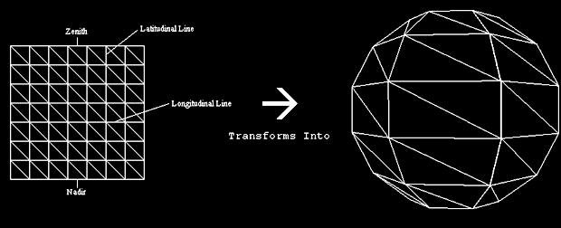
Now, if you are paying close attention, you may notice that we do have a slight problem. While we can define each longitudinal oriented band as a triangle strip, there is no way to "break" the strip to jump to the next "row". This is a true problem, and is solved by using degenerate triangles. (More specifically in our case - triangles that are infinitely thin). I will touch on this more in a moment, once I discuss how we pinch the bands.
Spin me Right Round
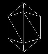
At this point, let's discuss a specific sphere tessellation. It will be a simple sphere, composed of three bands, with each band having three quadrilateral surfaces (or 6 triangles). The top band will be pinched at the top to form the Zenith, and the bottom band will be pinched to form the Nadir. The object will appear similar to a prism with pinched endpoints.
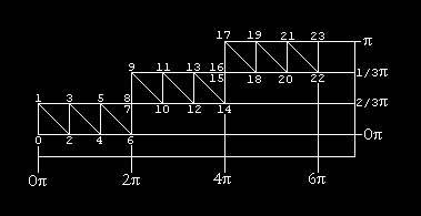
Now, let's unroll the mesh. There will be a total of three bands. The first band will start at the bottom of the sphere, or closest to Nadir. The eight vertices of the band will be rotated so the band forms a cylinder. Vertices 0 and 1 lie on 0p (0' rotation) (Longitude), and vertices 6 and 7 lie on 2p, (360∞ rotation) (Longitude). Hence, vertices 6 and 7 are identical in position to 0 and 1.
Now, if we continued our path mesh, you will also notice that vertex 8 and 7 are also identical. The triangle generated by 6,7,8 and 7,8,9 is infinitely thin. These two triangles allow us to begin the next row. Step by step we progress northwards towards the zenith creating bands along the way. Notice ñ we only progress from 0 to 180 or 0 to p in latitude ñ this is because each band revolves around the y axis a full rotation, so progressing to the "back" of the sphere is not necessary.
Follow the Bouncing Ball (... er... Bouncing Point)
With the basic principles in hand, we now need to generate these points (vertices), in the correct order. It would especially be nice to define a function f(i) where the function returns the x,y,z cords for a given vertex [i]. That is exactly what we are going to do next. However, at this point ñ let us make a simplification. Each band will be given exactly 2x points. In the above example, the band had 23 points. This will enable us to do some bit masking to give us a relatively compact solution.
To generate the mesh, we will create a single vertex starting at the Nadir <0,-R,0> [for a sphere of radius R]. We will bounce this point around ñ going to point 1, 2, 3 etc... generating each of the points by rotating the point along the X axis (aligning it to it's latitudinal position), followed by the Y axis (longitudinal position).
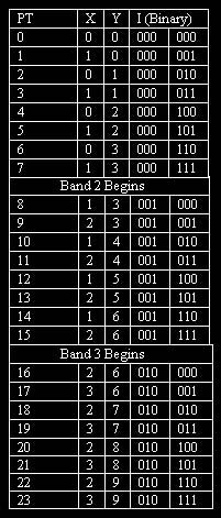
For a moment let's forget that a full rotation is in one band, and that we are dealing in angles. Instead, let's think of the rotation as in simply a arbitrary unit measure of angle. Each quad is equal to one unit of angular arc. If we think in these terms, we can define a table of values that summarize our traversal across the mesh.
Point 0 ñ the first point, starts with unit 0 for both x and y. Point 1 is slightly more vertical than point 0. It resides at 1,0. Now this probably seems counterintuitive ñ but remember I'm still talking about underlying rotation. It's rotation along the X-axis that results in movement of a point up or down along a longitudinal line. Point 3 is back at the Nadir. Point 4 is both more vertical and horizontal, and resides at 1,1. See if you can fill out the rest of the table.
 Now that we've defined the table, we need to create some algorithms to give us X value and Y values from the table. This will allow us to figure out where our bouncing ball has bounced.
The x value is pretty simple. In band one, it oscillates from 0 ñ 1. Flipping each time. In the second band, it does the same thing ñ but +1. In the third band, same scenario (but this time +2). With this we can construct the formula:
X=(I & 0b000001) + I( >> Band_Power)
Note ñ band power is the x from 2x = Total Vertices Band. In our case, we have 8 vertices, so Band power is 3. The first part of the sum gives us the oscillation value (0...1...0...1).. the second part increases by one each time we have a new band. This is possible because we forced the number of points in a band to be a power of two. This is also the reason why the table breaks the binary value of I into it's high order 3 bits and it's low order 3 bits.
The calculation of the formula for y is a little more complicated. The first thing we need to do is generate the pattern that we see in the first band. In this situation we are taking the lowest 3 bits; and dropping the last one. This gives us our sequence 0,0,1,1,2,2,3,3. The sequence will be the same for each band as it's based on the low order bits.
Now, we have to add something for each band. When we get to the second band, our Y value starts at 3. In the third band ñ it starts at 6. In fact, it is equal to the band number we are in (if we index the bands starting at 0) * the number of square sections in the band. The reason? Because our sphere is symmetrical ñ we have the same number of squares in a band as we have bands. This gives us the formula:
Now, armed with the formulas that give us our X angle and Y angle in units; we have to convert those units to radian angles. We can do this by defining sectional arc as 6.28/Sections_In_Band (notice we are taking about square sections. Our Sectional Arc in our example is 6.28/3. To get our actual Y rotation value, we multiply our unit Y (as defined above) by sectional arc. We do the same with X ñ however... remember that we don't rotate x a full 360∞. So, to compensate we take the X angle, multiply it by sectional arc and divide it by 2.
x_angle*=Section_Arc/2.0f; // remember - 180∞ x rot not 360
y_angle*=Section_Arc.
Rotating a Point Around the Origin.
Now that we've succeeded in generating the angles that represent our point in a journey around the triangle strip, we need to actually rotate the point. To do this we will use the standard formulas for rotation of a point around the X, Y or Z axis. For each rotation around an axis, there are two equations. There isn't a third equation, as when you rotate around an axis, your value for that axis (x,y,z) does not change. For example, your Z value for a point will not change if you rotate a point around the Z axis. Etc.
Here the following formulas:
Z Axis Rotation
      New_X = x * cos(z_angle) -  y * sin(z_angle)
      New_Y = y * cos(z_angle) +  x * sin(z_angle)
X Axis Rotation
      New_Y = y * cos(x_angle) - z * sin(x_angle)
      New_Z = y * sin(x_angle) + z * cos(x_angle)
Y Axis Rotation
New_Z = z * cos(y_angle) ñ x * sin(y_angle)
New_X = z * sin(y_angle) + x * cos(y_angle)
Did you take my word on it? I didn't think so. So, let's look at one of these in detail.
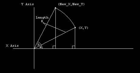
In the diagram, we are rotating point X,Y by angle A. We then rotate again by angle b. Now, let me introduce some trigonometric identities. [Take my word on these okay?].
cos(a+b) = cos(a)cos(b) - sin(a)sin(b)
sin(a+b) = sin(a)cos(b) + cos(a)sin(b)
Now, our previous point (X,Y) can be expressed as functions of sine and cosine. Recalling that cosine is the ratio of the adjacent side to the hypotenuse (or in our case R) we can calculate X as R*cos(a). Sine is the ratio of the opposite side to the hypotenuse (still R) so we can calculate Y as R*sin(a). So... X,Y can be respresented as:
X = R*cos(a)
Y = R*sin(a)
Now, using this and the identities ñ we can calculate Z axis functions for a given angle as follows:
New_X   = R*cos(a+b)
        = R*cos(a)*cos(b) - R*sin(a)*sin(b)  [care of trig identity]
        = X*cos(b) - Y*sin(b) [our formula!]


New_Y   = R*sin(a+b)
        = R*sin(A)*cos(b) + R*cos(a)*sin(b)  [care of trig identity]
        = Y*cos(b) + X*sin(b) [our formula!]
The Final Formula
Now, recall we are rotating a point <0,-R,0>. We are first rotating on the X axis ñ to get the right elevation or (latitude), and then rotating along the Y axis to get the right longitude. Let's start (note I'm going to use Y' to mean "new Y" and "y''" to mean "newer Y".
Y Axis Rotation:
Y' = -R * cos(X_Angle) ñ Z * sin(X_Angle)
Z' = -R * sin(X_Angle) + Z * cos(X_Angle)
Now, you might remember Z is 0! So the last two parts cancel out! Leaving:
      Y' = -R * cos(X_Angle)
      Z' = -R * sin(X_Angle) + Z * cos(X_Angle)
Now we start our Y axis rotation, with the new Z' and Y'. Again, as X is still 0 ñ the last parts cancel out. Note (there was no X' as X remains the same during a X axis rotation)
Z'' = Z' * cos(Y_Angle) ñ X * sin(Y_Angle)
X'' = Z' * sin(Y_Angle) + X * cos(Y_Angle)
Substituting our Z' in our equations:
      X = -R * Sin(X_Angle) * Sin(Y_Angle)
      Y = -R * Cos(X_Angle)
      Z = -R * Sin(X_Angle) * Cos(Y_Angle)
Pulling It All Together (Code)
Alas! It's time for a code example. Here is the code snippet, in all it's under-optimized glory. There are a few tweaks however. The first one is R. Since R is always negative = why not simply set
R = -R? Also, you will see an extra *-1 in the Y angle. This is because Direct 3d is a "three-dimensional left-handed Cartesian coordinate system."... and the rotation equations we used are for a "three-dimensional right-handed Cartesian coordinate system".
What was that? Well in short ñ it's different ways to measure rotation of angles. If you hold on to an axis with your left hand and point your thumb to the + side of the axis ñ the way your fingers curl is positive rotation. In the right handed system it's the same thing ñ but you use your right hand. I'll spare any pictures; as I'm not much of an artist. Just think about it for a few moments and it should make sense.
Anyway! Here is the code! [You might also want to check the bonus pack for Simple_Spheres.cpp and the executable.]
#include <math.h>
#include <stdio.h>
#include <conio.h>
#define Band_Power 4 // 2^Band_Power = Total Points in a band.
#define Band_Points 16 // 16 = 2^Band_Power
#define Band_Mask (Band_Points-2)
#define Sections_In_Band ((Band_Points/2)-1)
#define Total_Points (Sections_In_Band*Band_Points)
// remember - for each section in a band, we have a band
#define Section_Arc (6.28/Sections_In_Band)
const float R = -10; // radius of 10
int main(int argc, char* argv[])
{
int i;
float x_angle;
float y_angle;
for (i=0;i<Total_Points;i++)
{
// using last bit to alternate,+band number (which band)
x_angle=(float)(i&1)+(i>>Band_Power);
// (i&Band_Mask)>>1 == Local Y value in the band
// (i>>Band_Power)*((Band_Points/2)-1) == how many bands
// have we processed?
// Remember - we go "right" one value for every 2 points.
// i>>bandpower - tells us our band number
y_angle=(float)((i&Band_Mask)>>1)+((i>>Band_Power)*(Sections_In_Band));
x_angle*=(float)Section_Arc/2.0f; // remember - 180∞ x rot not 360
y_angle*=(float)Section_Arc*-1;
printf("{%f,%f, %f },\n",
R*sin(x_angle)*sin(y_angle),
R*cos(x_angle),
R*sin(x_angle)*cos(y_angle));
}
printf("Press any key\n");
getch();
return 0;
}
Conclusion!
Whew! That's quite the tutorial! We've accomplished our objectives of creating a simple sphere generation tool. The code spits out the x,y,z coordinates for a Triangle Strip. You might already see some places to optimize ñ for example we are calculating R*sin(x_angle) twice. Other areas! You bet! I wish you happy tweaking. And remember if you make something really cool, need some help, or have some good tweaks ñ let me know!